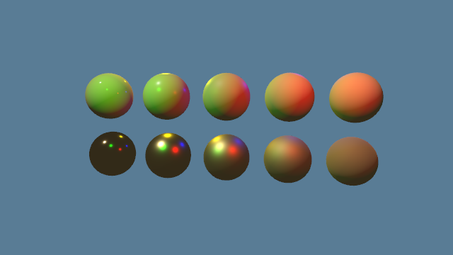
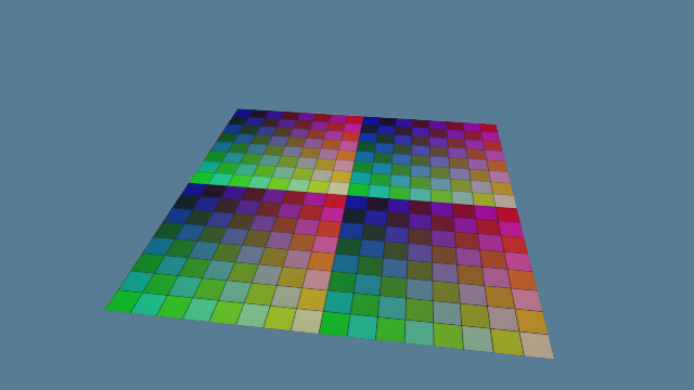
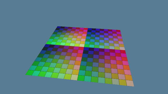
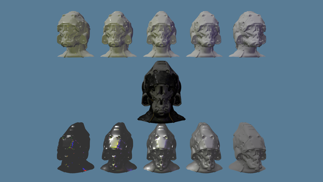
Praxis · M3 · ticket #199 · PRs #243, #245, #246, #247

How the lit pass turns light into colour

Ticket #199 rewrote how the lit pass shades a pixel, from primary sources: glTF 2.0's metallic-roughness BRDF exactly as its Appendix B writes it, point lights that fall off by inverse square inside KHR_lights_punctual's range window, and an ambient light and a background that each Reference scene sets for itself. This guide builds the shading up one term at a time, from what a BRDF is to what the new lit pass costs, with the oracles that check each term against its source.

Provenance. #199 landed in four PRs, all merged: #243, #245, #246 and #247, the last, which completes it as db3ef10. Code facts were read at 6764239, #247's last code commit (its final head, e9a327b, adds only CI's software-Vulkan Goldens), whose shading main now holds. The project's owner accepted the lit-pass cost on 2026-10-22, and later that day accepted #199's images at visual check 2, judged together with #200's HDR on #256, #200's last PR. Since then #200, #201, #203, #205 and #260 have changed the lit pass around this shading: it resolves exposed colour into an HDR target, lights each pixel with its Froxel's point lights and reads its shadows from a shadow mask (chapter 12).

Chapter 1

What a BRDF is

A pixel of the lit pass shows the light that one point of a surface sends towards the camera. That depends on the light arriving, on the directions involved, and on the surface. A bidirectional reflectance distribution function, or BRDF, describes the surface's part. In the words of glTF 2.0's Appendix B: "For a pair of directions, the BRDF returns how much light from the incoming direction is reflected from the surface in the outgoing direction."

Praxis measures light in glTF's units (ADR 0023). Light arriving at a surface is illuminance, in lux, lumens per square metre. Light leaving it in one direction is luminance, in candela per square metre, which is lumens per square metre per steradian: the quantity the lit pass writes for each pixel. The BRDF is the ratio between them, the luminance that leaves towards one direction per unit of illuminance that arrives from another, so its unit is per steradian. Rendering texts write the same equations with radiance and irradiance, the radiometric quantities in watts; the photometric ones are those weighted by the eye's sensitivity (Lagarde and de Rousiers 2014, §4.3). Until #200 the scenes' values are relative; HDR Pipeline Explained covers the units and exposure.

Four unit vectors describe the geometry, each pointing away from the shaded point, as Appendix B defines them: N, the surface normal; L, towards the light; V, towards the eye; and the half vector H = normalize(L + V). Every term of the shading reads cosines between them: N·L, N·V, N·H and V·H.

N H L to the light V to the eye θL θV shaded point surface
The four vectors, in Appendix B's notation: unit vectors from the shaded point. N·L is the cosine of θL and N·V of θV. H lies halfway between L and V, so H·L equals H·V.

A punctual light arrives from one direction, so it needs no integral. The luminance it sends towards V is f(L, V) E (N·L)+. E is the illuminance on a surface facing the light; N·L scales it down as the surface turns away, and the + clamps a light behind the surface to zero. reflected_luminance computes exactly this, the term every light adds to a pixel.

luminance towards V = f(L, V) × E × max(N·L, 0)

Appendix B states three rules for a BRDF in a physically accurate simulation: it "MUST be positive, reciprocal, and energy conserving". Reciprocity means f(L, V) = f(V, L), so the light and the eye can swap places. Energy conservation means the surface reflects at most what it receives: for every V, ∫ f(L, V) (N·L) dω, summed over every direction L of the hemisphere, is at most 1 (PBR, §5.6.1). That integral is the surface's directional albedo, and chapter 7 measures it.

Before #199 the lit pass shaded with a function called cook_torrance, and spec #188 summed up its sources: "The falloff and the ambient constant come from a tutorial (#91), the geometry term is Schlick's approximation with Disney's remap". The spec asked for a lit pass that follows "glTF 2.0 Appendix B's BRDF exactly (D, V, F and its diffuse and specular mix), each function with an oracle, so that glTF content renders as authored and every term traces to a primary source", and for the tutorial-derived constants to go.

Four PRs

The work came to about 1,200 changed lines without Goldens, three times the ticket's ceiling, so the split comment on #199 cut it into four PRs, each rebased on the one before.

PRWhat it changesChanged linesImages
#243The surface decode in a shared function, and the glossary's names258none change
#245Appendix B's D and height-correlated V206highlights
#246Appendix B's dielectric and metal mix, gathered by lobe; reflected_luminance370silhouettes, and the helmet's fractional metallic
#247Inverse-square falloff in KHR's range window; ambient and background per scene363most scenes
The four parts, in merge order, with each PR's own count of changed lines, Goldens not counted. Chapter 10 has the images.
Chapter 2 · PR #243

Metals and dielectrics

Appendix B builds every glTF surface from two simpler ones. Its material is a linear blend, mix(dielectric_brdf, metal_brdf, metallic), a model it credits to Burley 2012 and says many renderers adapted. The Material's metallic factor, times its texel, picks the blend.

A metal, in Appendix B's words, reflects "most illumination, only a small portion of the light is absorbed by the material". Its reflectance would need a wavelength-dependent refractive index and extinction coefficient; glTF folds both into the base colour, which becomes the metal's reflectance at normal incidence, F0. At grazing incidence, the reflectance of any material approaches white, 1. Appendix B's metal BRDF is a specular lobe alone, tinted by its Fresnel term, so a metal's colour is the colour of its reflections.

A dielectric transmits "most of the incident illumination into the interior of the object". In most plastics, particles inside absorb or scatter that light, and what scatters back out gives the surface its colour. Appendix B therefore models a dielectric as two lobes mixed by its Fresnel term: a specular lobe for the reflection at its surface, and a Lambertian diffuse lobe, the base colour over π, for the light that went in. Its index of refraction is fixed at 1.5, "a good compromise for most opaque, dielectric materials", which gives F0 = ((1 − 1.5) / (1 + 1.5))² = 0.04: a dielectric reflects 4% of the light that meets it head on, whatever its colour.

metal_brdf = conductor_fresnel(f0 = baseColor, bsdf = specular_brdf(α = roughness²)) dielectric_brdf = fresnel_mix(ior = 1.5, base = diffuse_brdf(color = baseColor), layer = specular_brdf(α = roughness²)) material = mix(dielectric_brdf, metal_brdf, metallic)

A metallic between 0 and 1 is a blend. Appendix B allows it where anti-aliasing or mip-mapping leaves "a portion of metal and a portion of dielectric within a texel", and for layering by blending parameters. SciFiHelmet's metallic Texture is fractional, about 0.2 to 0.3 over most of it (PR #246), so chapter 6's mix matters there.

Decoding the surface

Shading starts from the surface's values at the pixel. The lit pass's entry point samples every Texture first, before any light, so no textureSample runs under non-uniform control flow. The owner's architecture review on #199 notes that this keeps the review checklist's uniformity rule "by construction (naga does not check it)". The entry point then calls decode_surface, a pure function in the shared shading part since #243, which multiplies each Material factor by its texel (base colour and its alpha, metallic from the cooked metallic-roughness texel's green and roughness from its red, and emissive) and takes occlusion from its texel alone. glTF stores roughness in green and metallic in blue; the cooker moves them into a two-channel BC5 Texture, roughness in red and metallic in green (ADR 0018). A roughness below 0.04 rises to it, for the reason in chapter 4.

#243 also took the glossary's names, a rename #98 had deferred to this rewrite. texture_indices became layers, a Layer per Channel, and the cooker's normal_map became the normal Texture. Rewriting the Metal Goldens changed none of them, and the lit pass's GPU time stayed within each measuring session's spread.

Chapter 3 · PR #246

Fresnel

How much of the light a surface reflects, rather than lets in, depends on the angle it arrives at. That share is the Fresnel term, F. Appendix B uses Schlick's 1994 approximation of the Fresnel equations for metals and dielectrics alike:

F = F0 + (1 − F0) (1 − |V·H|)⁵

F equals F0 where V meets the reflecting facet head on, and rises to 1 at grazing. The angle is the one between V and H, the normal of the facets that mirror light from L into V (chapter 4), since those facets do the reflecting. H·L equals H·V, so one cosine serves both directions.

fresnel_weight computes the weight w = (1 − |V·H|)⁵ once per light, and both lobes read it. It multiplies the power out, c² × c² × c with c = 1 − |V·H|, where pow(c, 5.0) would read more simply. V and H are unit vectors only to f32's rounding, so their dot product can come out a step past 1, and c a hair below 0. WGSL leaves a negative base outside pow's domain, since pow may be computed as exp2(y × log2(x)), and outside a domain WGSL "may instead yield an indeterminate value". Multiplied out, c⁵ is a negligible negative number and F stays F0. The old fresnel_schlick passed pow one minus a cosine clamped only below, at 0.

The oracle fresnel_rises_from_the_base_reflectance_to_one_at_grazing checks three F0s at once, 0.04, 0.5 and 1. F is F0 at |V·H| = 1 and one f32 step past it. At ±0.5 it adds 1/32 of what F0 misses, so a dielectric's 0.04 becomes 0.07, and at 0 it is 1.

Appendix B's discussion records the approximation's limits. Schlick's F matches the full Fresnel equations well for indices of refraction from 1.2 to 2.2, and it misses the dip in reflectance that metals often show near grazing. Appendix B still suggests it for metals, since glTF gives metals no extra colour that would describe the dip.

Chapter 4 · PR #245

D, the facets' normals

Appendix B's specular lobe comes from microfacet theory. A surface is taken to be a field of tiny flat mirrors, microfacets, whose normals scatter around N; roughness 0 is a smooth mirror and 1 a rough surface. A facet mirrors light from L into V only if its normal is H, so the highlight follows how densely the facets face H. That density is the normal distribution function, D.

Appendix B's D is the Trowbridge-Reitz distribution, which Walter et al. 2007 developed independently and named GGX, finding it a better fit for measured data than the Beckmann distribution of Cook and Torrance:

D = α² χ⁺(N·H) / (π ((N·H)² (α² − 1) + 1)²)

χ⁺ is 1 for a positive argument and 0 otherwise, so no facet faces below the surface. The width α is roughness², a mapping Burley 2012 chose because it "results in a more perceptually linear change in the roughness".

D is a density over directions, normalised so that the facets' areas, projected onto the surface, add up to the surface's own: ∫ D(H) (N·H) dω = 1 over the hemisphere (Walter et al. 2007, eq. 4). It peaks along the normal at 1 / (π α²). The oracle distribution_ggx_integrates_to_one_over_the_hemisphere checks both: the integral to within 10⁻⁵ at roughness 0.25, 0.5, 0.75 and 1, and the peak at roughness 0.5, which is 16/π.

The roughness floor

As roughness falls, that peak grows without bound. At α = 0, D becomes a delta function and the BRDF divides by zero, and the specification's source now says implementations "should therefore never use α = 0": they should clamp α to a small positive value, or treat the surface as an ideal mirror on a separate code path. The published 2.0.1 page, last updated in 2021, predates that note; the AsciiDoc source on GitHub carries it. It predates two more revisions to Appendix B's informative sample implementation, both of which Praxis follows: 2.0.1 gives the separable form of Smith's masking-shadowing, where the source now gives the height-correlated V, and a simplified combination of the two lobes, where the source now gives the "full code" that mixes dielectric and metal exactly. The material's structure, mix(dielectric_brdf, metal_brdf, metallic), is the same in both. Praxis keeps roughness at or above MINIMUM_ROUGHNESS, 0.04, the roughness floor, as the lit pass already did before #199. α is then at least 0.0016, and D's peak at most 1 / (π × 0.0016²), about 124,000 per steradian by this guide's arithmetic.

ADR 0023 counts what that needle means for HDR: under 100,000 lux, a dielectric's sun glint at roughness 0.04 peaks at 1.24 × 10⁸ cd/m², 10.9 stops past fp16's largest value, 65504. This guide's arithmetic reproduces that peak with the sun and the eye both along the normal, where chapter 5's visibility term V is 1/4 and F = 0.04: 124,340 × 1/4 × 0.04 × 100,000. It is the lowest such peak: as the sun sinks, the eye at its mirror direction, the glint grows, to 4.4 × 10⁸ cd/m² at 60° from the normal, 12.7 stops past 65504, by the same arithmetic.

Where f32 runs short

At the floor's peak, N·H = 1, the textbook denominator (N·H)² (α² − 1) + 1 should come to α² = 2.56 × 10⁻⁶. f32 first computes α² − 1, close to −1, where neighbouring f32 values lie 2⁻²⁴ apart, about 6 × 10⁻⁸. Adding 1 then leaves α² plus whatever that rounding did, which is about a thousandth of α²: by this guide's arithmetic the denominator comes out 0.12% high, and D, which divides by its square, 0.23% low, the figure PR #245 gives.

#245 sums the same denominator in another order, (N·H)² α² + (1 − N·H)(1 + N·H), which equals the textbook form, since (1 − N·H)(1 + N·H) = 1 − (N·H)². Summed this way, the small quantities are computed directly, never as what is left of −1 after adding 1, and in the PR's words "the sum keeps every term to a few ulps".

D at N·H = 1, roughness 0.04ValueOff by
Appendix B's formula, in f64124,339.8reference
Textbook denominator, each step rounded to f32124,048.9−0.234%
#245's summed denominator, each step rounded to f32124,339.8under 0.00001%, within one f32 step
The cancellation at the floor's peak, by this guide's arithmetic: each operation rounded to f32 with JavaScript's Math.fround. A GPU may fuse operations and round differently; PR #245 gives 0.23% for the textbook form.

distribution_ggx_matches_appendix_b_from_the_roughness_floor_to_one compares D with Appendix B's formula in f64 at N·H from −0.5, below the horizon, through 0.99999 to 1, and for α from the floor's 0.0016 to 1, within 4 × 10⁻⁶ of each value. With the textbook denominator in f32 it fails (PR #245). The integral test leaves the floor out, as it did before #199: there D integrates to 0.9991, up from the 0.998 recorded for the old form in the project's planning issue, #17, and the rest is f32's rounding of cos θ itself, so the floor is checked against the f64 reference instead.

Chapter 5 · PR #245

V, masking and shadowing

Not every facet that faces H takes part. Some are hidden from the eye behind other facets, which is masking, and some are hidden from the light, which is shadowing. The masking-shadowing function G gives the share of the facets facing H that are both seen and lit. Appendix B's specular lobe is the microfacet BRDF G D / (4 |N·L| |N·V|), and Appendix B folds G and that denominator into one visibility term, V, which is not the direction towards the eye (the published 2.0.1 text gives both the same letter, as this guide does; the current source writes the visibility term ν), so the lobe is V × D:

V = G / (4 |N·L| |N·V|) = χ⁺(H·L) χ⁺(H·V) ───────────────────────────────────────────────────────── 2 (|N·V| √(α² + (1 − α²)(N·L)²) + |N·L| √(α² + (1 − α²)(N·V)²))

This is the height-correlated form of Smith's masking-shadowing function, which Appendix B takes from Heitz 2014. Heitz gives the reason for the correlation: "the more a microfacet is elevated within the microsurface, the more the probabilities of being visible for the outgoing direction (unmasked) and for the incident direction (unshadowed) increase at the same time." The separable form, which multiplies masking by shadowing as though they were independent, "always overestimates shadowing since some correlation always exists" (Heitz 2014, §6).

Before #245 the lit pass used a separable form, each factor in Schlick's approximation with Disney's roughness remap, k = (roughness + 1)² / 8. Burley 2012 remapped roughness for G after comparing with measured data, and after artists found the specular "too hot" for small roughness values. Karis 2013 kept the remap for analytic lights only, warning that "if applied to image-based lighting, the results at glancing angles will be much too dark". Issue #17 listed that under its heading "Not yet specified", and milestone M3 took Appendix B's form instead. The old form also divided by 4 (N·V)(N·L) + 0.001, the 0.001 there to keep the denominator off zero.

The new V needs no such constant. Where N·L and N·V are both 0, the light and the eye both lie along the surface and the denominator is 0; smith_visibility returns 0 there, so a light along the surface reflects none. χ⁺(H·V) is 0 when V lies behind the facets facing H. Appendix B also writes absolute cosines, |N·L| and |N·V|, where cook_torrance clamped them at 0; #246's switch to them changed images only at silhouettes (chapter 10).

smith_visibility_matches_appendix_b_and_keeps_g_within_zero_to_one checks V against Appendix B in f64 for cosines from 0, through 10⁻⁴ and 0.01, to 1, and α from the floor to 1, within 4 × 10⁻⁶ of each value. It also checks that G = 4 |N·L| |N·V| V stays within [0, 1]. Dropping the 2 from V's denominator makes it fail (PR #245).

Chapter 6 · PR #246

The mix, gathered by lobe

Appendix B's "full code" puts the terms together:

fresnel_w = (1 - abs(VdotH))^5

diffuse_brdf = (1 / π) * baseColor.rgb
specular_brdf = D(roughness^2) * G(roughness^2) / (4 * abs(VdotN) * abs(LdotN))

dielectric_f0 = 0.04
dielectric_fresnel = dielectric_f0 + (1 - dielectric_f0) * fresnel_w
dielectric_brdf = mix(diffuse_brdf, specular_brdf, dielectric_fresnel)

metal_fresnel = baseColor.rgb + (1 - baseColor.rgb) * fresnel_w
metal_brdf = metal_fresnel * specular_brdf

material = mix(dielectric_brdf, metal_brdf, metallic)
glTF 2.0, Appendix B, "Metal BRDF and Dielectric BRDF", verbatim from the specification's AsciiDoc source at 7cee0fc (lines 3838 to 3850; Khronos, CC BY 4.0). The published 2.0.1 page gives a simplified mix in its place (chapter 4). Its G over 4 |N·V| |N·L| is chapter 5's V.

Write w for fresnel_w, S for the specular lobe D × V, c for the base colour and m for metallic. The dielectric's Fresnel is Fd = 0.04 + 0.96 w and the metal's is Fm = c + (1 − c) w, and the material expands to (1 − m)((1 − Fd) c/π + Fd S) + m Fm S. Gathered by lobe:

diffuse lobe: (1 − m) (1 − F_d) c / π specular lobe: ((1 − m) F_d + m F_m) S

Schlick's F is linear in F0: F(F0) = F0 + (1 − F0) w = F0 (1 − w) + w. A weighted average of two Fresnel values, with weights that sum to 1, is therefore the Fresnel value at the same average of their F0s:

(1 − m) F(0.04) + m F(c) = F((1 − m) 0.04 + m c) = F(mix(0.04, c, m))

So the dielectric's specular lobe and the metal's merge into one, whose Fresnel is F at the mixed F0. That F0 depends on the surface alone, and no light changes it. metallic_roughness_brdf computes Appendix B's BRDF in this gathered form, with the diffuse share as one number:

let alpha = surface.roughness * surface.roughness;
let specular = distribution_ggx(normal_dot_half, alpha)
    * smith_visibility(normal_dot_light, normal_dot_view, view_dot_half, alpha);
// The mix, gathered by lobe (lines 120 to 125).
let weight = fresnel_weight(view_dot_half);
let dielectric_fresnel = DIELECTRIC_BASE_REFLECTANCE
    + (1.0 - DIELECTRIC_BASE_REFLECTANCE) * weight;
let diffuse_share = (1.0 - surface.metallic) * (1.0 - dielectric_fresnel) / PI;
let base_reflectance = mix(
    vec3<f32>(DIELECTRIC_BASE_REFLECTANCE),
    surface.base_color,
    surface.metallic
);
let specular_fresnel = base_reflectance + (vec3<f32>(1.0) - base_reflectance) * weight;
return diffuse_share * surface.base_color + specular_fresnel * specular;
src/render/shaders/shading.wgsl, lines 117 to 136 at 6764239, indented less, with the comment on lines 120 to 125 shortened. mix(a, b, t) is a × (1 − t) + b × t.

The two forms are the same function, and the f64 oracle compares the gathered one with Appendix B's own code. They differ in the work done per light. Mixed as Appendix B writes it, with two three-channel BRDFs built for every light, the dielectric's and the metal's, each with its own Fresnel, then mixed, the lit pass took 7 to 25 µs longer than part 2 at 2560×1440 on the M4 Pro, far-coplanar 24.6 µs and helmet 23.2 µs; the shader's comment puts it at up to 5%. Gathered by lobe, a focused session of three rounds on the five heaviest scenes measured −0.9 to +5.3 µs against part 2 (PR #246).

The old cook_torrance weighted its diffuse lobe by 1 − F at an F0 already blended by metallic, which is the simplified mix the published 2.0.1 text gives as its final BRDF. PR #246 notes that this agrees with Appendix B's full code only where metallic is 0 or 1. At metallic 0.5, for example, the full code weights the diffuse lobe by 1 − F(0.04), and the old code by 1 − F(mix(0.04, c, 0.5)).

No Golden scene has a fractional metallic, so #246 changed the Goldens only at silhouettes, where chapter 5's absolute cosines replaced the old clamp, mostly on metals. On SciFiHelmet, metallic about 0.2 to 0.3 over most of it, the mix itself moved pixels by up to 23 steps (PR #246).

reflected_luminance wraps the BRDF into the per-light term f(L, V) E (N·L)+, from unit vectors. Where L and V point in opposite directions, L + V is zero and has no direction. The shader then scales it by the inverse square root of at least 10⁻³⁰, which leaves H zero instead of NaN, and χ⁺ zeroes the specular lobe.

whole BRDFspecular lobediffuse lobe
Radius:
Term at this L and VValue
N·L, N·V
N·H, V·H
α = roughness²
D, the distribution
V, the visibility term
w = (1 − |V·H|)⁵
F, specular lobe (R G B)
Diffuse share
f(L, V) (R G B)
f(V, L), swapped
f (N·L)⁺ for illuminance 1
Base colour:

Live demo. The BRDF in the plane that holds N, L and V, from the same formulas as shading.wgsl. Along each direction V, the curve's distance from the shaded point is the luminance reflected that way for illuminance 1 from the light, f(L, V) (N·L)+, averaged over the three colour channels and scaled to the curve's own peak; the log radius shows six decades below the peak. Drag across the plot, or use the sliders, to move V, and swap L and V to see reciprocity: f(V, L) in the table equals f(L, V). Roughness below 0.04 is raised to it, as decode_surface does. Simplified: the page computes in f64 where the shader uses f32, and shows one plane, while the lobe extends out of it in 3D.
Chapter 7 · PRs #245, #246

The oracles

Every new or changed shading function has an oracle in src/render/shader_function_tests.rs. The test appends a compute kernel to the shared shader parts, so the expression it evaluates calls the very functions the passes run; it runs them over test vectors in one dispatch on the GPU and reads the results back. It compares them with values worked out apart from the shader: literals, analytic results, and f64 references written from the source as the source writes it. reference_brdf is Appendix B's "full code", line for line.

f32 cannot match f64 exactly, so each check states its tolerance. The BRDF's terms must land within 4 × 10⁻⁶ of the reference, relative, and land within 2 × 10⁻⁶ on the M4 Pro. Shading from unit vectors gets 5 × 10⁻⁵: f32 rounds each direction and each cosine by about 10⁻⁷, which D, steep near its peak at the roughness floor, turns into up to 1.1 × 10⁻⁵ of the result.

Reciprocity

metallic_roughness_brdf_matches_appendix_b_and_is_reciprocal runs 675 cases: three roughnesses (the floor, 0.5 and 1), three metallics (0, 0.5 and 1), five view angles and five light angles (0°, 30°, 60°, 85° and 90°), and three azimuths (0°, 90° and 180°), with pbr-sweep's gold base colour, (1.0, 0.71, 0.29). Each case is checked against Appendix B's full code in f64, then evaluated again with L and V swapped, which must give the same value. PR #246 lists what it catches: "Appendix B's simplified mix", metallic's mix reversed, and the diffuse lobe missing its 1/π.

The white furnace

Energy conservation is checked in a white furnace, where light of the same strength arrives from every direction of the hemisphere. What a surface sends towards V there adds up to its directional albedo, which PBR describes as "the total reflection in a given direction due to constant illumination over the hemisphere". A surface that conserves energy reflects at most 1, all it receives. The reflected-luminance oracle sums a white metal's reflection over 16,200 directions, cells of 1° by 2°, at roughness 0.5 seen from 0°, 60° and 85°, and at roughness 1 seen from 0° and 85°; every sum is at most 1. It fails without the half-vector guard, with NaN, or with N·V in place of N·L.

A white metal reflects less than 1, and much less when rough. Appendix B's BRDF follows light for one bounce on the microsurface, and "the shadowing term suppresses light that intersects the microsurface a second time"; Heitz 2014 shows that such models "do not integrate to 1 even when parameterized on a 'perfect reflector' microsurface" (§3.5). Appendix B suggests adding multiple scattering whenever possible, which #199 does not do. Seen head-on at roughness 1, where D = 1/π and V = 1 / (2 (1 + N·L)), a white metal reflects 1 − ln 2 ≈ 0.307 of what it receives, by this guide's arithmetic, and the demo below sums the same.

The dielectric is not held to the bound, because Appendix B's own coupling breaks it. Its section "Coupling Diffuse and Specular Reflection" says that fresnel_mix "is not very accurate and breaks a fundamental property that a physically based BRDF must fulfill", energy conservation. A white dielectric at roughness 0.5 reflects 1.11 of what it receives at 85° (PR #246). Its diffuse lobe gives up only F at each light's own half vector, which stays small for most light directions even when V is grazing: 0.06 on average here. Its specular lobe gathers its light around the mirror direction, where F is larger, about 0.2 on average over the lobe and 0.65 at the mirror direction itself, and adds 0.18, as the demo below shows. Together they pass 1. Appendix B points to fixes, among them Kulla and Conty's 2017 coupling, which is energy conserving and needs a small precomputed table. Spec #188 asks for Appendix B's BRDF exactly, and the oracle tests what Appendix B specifies.

white metalwhite dielectricthe dielectric's diffuse lobe alone
Roughness:
White metal reflects
White dielectric reflects
Dielectric: diffuse + specular

Live demo. Directional albedo, the share of what it receives that a white surface reflects towards V, against the view angle, for a white metal (base colour 1, metallic 1) and a white dielectric (base colour 1, metallic 0), from the same formulas as shading.wgsl. Hollow circles mark the views the oracle checks at roughness 0.5 and 1, and PR #246's 1.11 for the dielectric at roughness 0.5 and 85°. Simplified: the page sums in f64 and on its own grids. It sums the diffuse lobe over light directions spread as cos θ, and the specular lobe over half vectors spread as GGX spreads them (Walter et al. 2007, eq. 35), each light the view mirrored about its half vector, so the needle at low roughness is not missed; the oracle sums 16,200 directions in 1° by 2° cells, at roughness 0.5 and 1 only. Each point of the curves sums 10,240 directions and stays within 0.012 of a converged sum up to 87°; the figures above sum 135,168 and stay within 0.003 up to 86° and within 0.008 nearer grazing.
Chapter 8 · PR #247

Point lights

KHR_lights_punctual defines glTF's lights as "parameterized, infinitely small points that emit light in well-defined directions and intensities", punctual lights. A directional light gives illuminance in lux. A point light emits in all directions from its position, with a luminous intensity in candela, lumens per steradian.

A point light's intensity spreads over a sphere of directions, and the area a bundle of them covers grows with the square of the distance (Lagarde and de Rousiers 2014, §4.4). The illuminance on a surface facing the light therefore falls as E = I / d², the inverse square law; KHR_lights_punctual says a point light's brightness "goes like the inverse square of the distance".

The old lit pass divided a point light's intensity by 1 + 0.09 d + 0.032 d², constants the ticket calls tutorial-derived and PR #247 traces to LearnOpenGL. For one intensity, that curve is dimmer than inverse square within about 1.06 m and brighter beyond, approaching 1/0.032 = 31.25 times brighter far away, by this guide's arithmetic.

The range window

Inverse square never reaches zero, so without a limit every light would reach every pixel and would have to be evaluated there (Filament's documentation). KHR_lights_punctual gives point lights a range, past which "rendering engines ignore the light". It asks that "attenuation should follow the inverse square law as closely as possible, although some non-quadratic falloff near the edge of the range may be used to avoid a hard cutoff", and recommends:

attenuation = max(min(1 − (d / r)⁴, 1), 0) / d²

The range window, the factor before the division, keeps 0.9375 of inverse square at half the range and falls to exactly 0 at d = r, staying 0 past it, by this guide's arithmetic. Filament's documentation, after Karis 2013, squares the same window; KHR's recommendation does not, and Praxis follows KHR.

The range has a second use in Praxis. #201 will cull point lights into Froxels, each listing the lights that reach it, and must match lighting with every light at every pixel within Golden tolerance. A light that reaches exactly 0 at its range lets culling drop nothing it contributes, which is why spec #188 asks for the window (story 22).

Working in distance²

point_light_attenuation works in distance² throughout. (d / r)⁴ is (d² / r²)², so the window needs no square root, and point_light_luminance takes one inverse square root of d² to turn the light's offset into its direction (PR #247).

fn point_light_attenuation(distance_squared: f32, range: f32) -> f32 {
    let ratio_squared = distance_squared / (range * range);
    let window = clamp(1.0 - ratio_squared * ratio_squared, 0.0, 1.0);
    return window / distance_squared;
}

// In point_light_luminance:
let distance_squared = max(dot(light_offset, light_offset), MINIMUM_LIGHT_DISTANCE_SQUARED);
let illuminance = intensity * point_light_attenuation(distance_squared, range);
let light_direction = light_offset * inverseSqrt(distance_squared);
return reflected_luminance(surface, normal, view_direction, light_direction, illuminance);
src/render/shaders/shading.wgsl, lines 173 to 177 and 193 to 196 at 6764239, indented less. MINIMUM_LIGHT_DISTANCE_SQUARED is 10⁻⁴, a square centimetre.

At d = 0, I / d² is infinite. Distance² is held at 1 cm² or more, as though the light were a sphere of 1 cm radius. Filament's documentation treats punctual lights "as spheres of 1 cm radius" (Filament is Apache-2.0), and Frostbite gives them "a size of 1 cm" (Lagarde and de Rousiers 2014, §4.4). A surface at a light is then lit finitely. Within 1 cm, the direction, the offset times the inverse square root of the held distance², shortens with the distance and is zero at the light itself, which has no direction from there, so the light adds 0 instead of NaN. #247's first form guarded the normalised direction instead and cost 6 to 8 µs more; the distance² form removed that.

PointLight gained range, "Metres from the light past which it adds nothing", positive and here finite, and each Reference scene authors one; the light uniform carries it in the w of each light's position (since #261, merged on 2026-10-23 as 7ee4ed6, each light's entry in a light buffer carries it). point_light_luminance multiplies the intensity by the attenuation and hands that illuminance to reflected_luminance. It is the per-light function the architecture review on #199 asked for, so the entry point only samples, decodes and sums.

point_light_attenuation_falls_by_inverse_square_to_zero_at_the_range checks the attenuation against KHR's formula in f64, from the same d², from 2 cm to past the range, and requires exactly 0 at and past it. point_light_luminance_attenuates_the_intensity_it_reflects places lights near and far, beside, above and below the normal, up to and past a 4 m range, and one at the shaded point itself, where the result must be 0. PR #247 lists the mistakes they catch: no distance floor, the window's ratio or the range not squared, the range doubled, and the light's direction flipped.

inverse square in KHR's windowinverse square, no windowthe old tutorial curve
#247's scene values:
Window at d
Inverse square in the window
Tutorial curve, old intensity

Live demo. The illuminance a point light gives a surface facing it, against distance, both axes logarithmic: inverse square inside KHR_lights_punctual's window, the same without the window, and the old tutorial curve at the old intensity. The window reaches exactly 0 at the range, where the curve leaves the chart; past it the light adds exactly 0. Below 1 cm the new curves are flat, since distance² is held at 1 cm² as in the shader. The presets are #247's scene values: the coloured lights went from intensity 1 to 9 with a range of 20 m, and minification's light from 30 to 300 with a range of 200 m. Values stay relative until #200. Simplified: the page computes in f64, and leaves out N·L and the BRDF, so this is the illuminance on a surface turned to face the light.
Chapter 9 · PR #247

Ambient and background

Before #199 the ambient term was a constant in the shader, 0.03 × base colour × occlusion, while the light uniform's ambient field was, in spec #188's words, "uploaded but never read". The background, the lit pass's clear colour, was a constant in main_pass.rs, (0.1, 0.2, 0.3).

#247 gives each Scene an Environment, a resource in the ECS World with a feature module of its own, src/environment/. It holds two of ADR 0023's quantities: the ambient illuminance, light every surface receives from all around, and the background luminance, seen wherever nothing is drawn. Its default is dark. Each Reference scene sets its own; prepare reads it once a frame and copies it into Frame data, into LightUniform.ambient_illuminance, which replaces the unread field, and into FrameData::background, the lit pass's clear colour. These are scene content: the glossary keeps ambient and background out of the Render switches.

The lit pass adds ambient_luminance: E/π times the base colour, darkened by occlusion. Under light of the same luminance L from every direction, the illuminance on a surface is E = πL (PBR, §5.5), so E/π is the luminance of the surroundings, and a surface sends back its directional albedo of it. The ambient term takes that albedo to be the base colour, which is about what a white-lit dielectric's diffuse lobe reflects, and about what a smooth or moderately rough metal reflects through its specular lobe, its F0 being its base colour. A rough metal reflects less under Appendix B's one-bounce BRDF, a white one at roughness 1 as little as 0.31 of what it receives seen head-on (chapter 7), so there the ambient term lights it about three times as much as its BRDF would.

Metals get the ambient too. It stands in for ADR 0020's irradiance probes, which arrive in M5, and ADR 0020 has "Rough specular reads the irradiance probes", so the probes will light metals as well. #247's first form lit only the dielectric's diffuse share; review restored the metals, which the old 0.03 term had lit. glTF applies occlusion to indirect light only: the occlusion texture marks "areas that receive less indirect lighting from ambient sources. Direct lighting is not affected."

The scenes' values

The new values are relative, like the old ones, until #200 re-authors every light, ambient and background in ADR 0023's units and gives each scene an EV100; HDR Pipeline Explained covers that step. Until then #247 keeps each subject lit about as before:

  • Ambient illuminance is 0.1 in every scene, a tenth of the sun's, whose illuminance is 1. Against the old 0.03, 0.1/π ≈ 0.032 moved far-coplanar and texture-wall by at most one step, inside tolerance.
  • The background stays (0.1, 0.2, 0.3), so background pixels do not change. It came from learn-wgpu's clear colour (MIT); review kept it as an authored per-scene value for #200 to re-author in cd/m².
  • The four coloured lights rise from intensity 1 to 9 and reach 20 m. At 3 m that gives the sun's illuminance, where the tutorial falloff gave 0.64 of it. Under inverse square, the old intensity would have left them at about a sixth of their old illuminance on the spheres.
  • minification's light rises from 30 to 300, which keeps its glint, and reaches 200 m, past the floor's far corners 83 m away.
Chapter 10 · all four PRs

What the images show

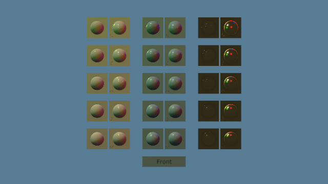
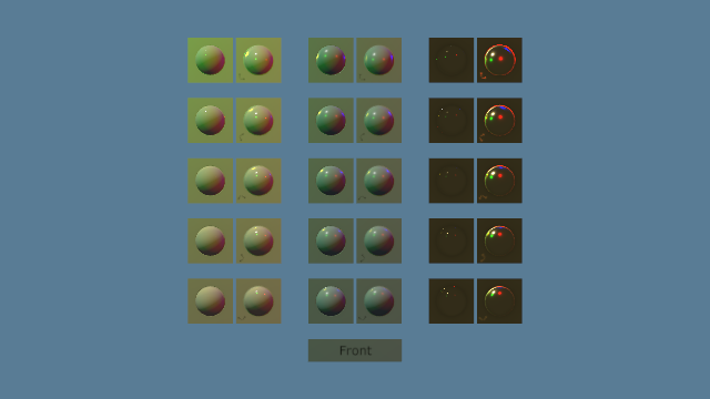
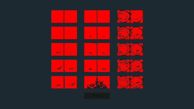
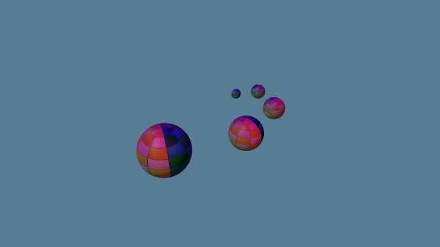
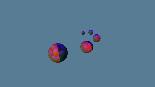
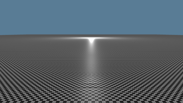
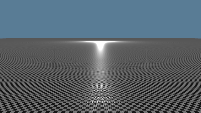
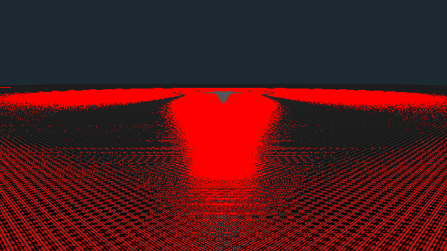
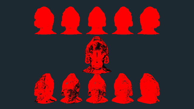
Each PR that changes an image carries before, after and difference images of the Metal Goldens, and of the helmet, which has no Golden. A Golden matches when no channel of any pixel moves by more than one 8-bit step; the PRs count the pixels past that and give the largest move, in steps. The software-Vulkan Goldens come from CI. The owner judged the images at visual check 2, on #256, #200's last PR, together with HDR, and accepted them on 2026-10-22.

  • #243: no image changes; every Metal Golden stayed byte-identical.
  • #245, D and V: highlights. minification's glint widens at grazing (85,143 pixels, up to 115 steps), pbr-sweep's highlights move (13,217 pixels, up to 72), and normal-tangent's (1,961, up to 136); the helmet moves 80,922 pixels by up to 85; uv-grid (21,798, up to 4), orrery (2,236, up to 10) and far-coplanar (3,059, up to 2) move too.
  • #246, the mix: silhouettes, mostly on metals: pbr-sweep 70 pixels by up to 8, normal-tangent's metal column 160 by up to 14, and the helmet 1,727 by up to 23, at its silhouettes and where its metallic is fractional.
  • #247, falloff and ambient: most scenes. minification's glint under inverse square (104,803 pixels, up to 91), pbr-sweep (35,026, up to 83), uv-grid (67,119, up to 55), normal-tangent (45,353, up to 64), orrery (8,530, up to 64) and the helmet (196,614, up to 84); far-coplanar and texture-wall move by at most 1.
Scene, #199 as a wholePixels past toleranceLargest moveImages
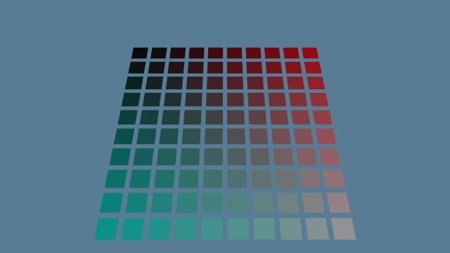
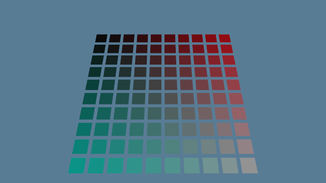
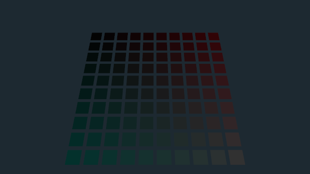
pbr-sweep36,12790before · after · difference
uv-grid67,18655before · after · difference
normal-tangent45,898157before · after · difference
far-coplanar8,6102before · after · difference
orrery8,56365before · after · difference
minification54,35475before · after · difference
texture-wallnone1before · after · difference
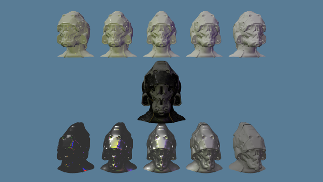
helmet, no Golden, 1280×720204,82684before · after · difference
#199 as a whole, from PR #247's table for visual check 2: before is main at fe08baa, after is #247's head. Each difference image dims the after image and marks in red each pixel with a channel past one step. Each PR's own table, linked above, has its part alone.
Chapter 11 · PR #247

What it costs

The ticket names one metric that must not regress: "GPU time of the lit pass (delta reported)". Each part was measured against the part before on the M4 Pro at 2560×1440, in interleaved rounds, and parts 1 to 3 stayed within the sessions' spread. For #199 as a whole, #247 ran four interleaved rounds of main before #199, at fe08baa, and of its own shading:

SceneBefore #199, µsAfter #199, µsDelta, µs
far-coplanar494.8 [0.9]501.2 [1.3]+6.5 (+1.3%)
helmet623.4 [1.8]630.8 [2.5]+7.4 (+1.2%)
minification552.5 [1.6]552.0 [1.0]−0.5
normal-tangent392.0 [4.8]394.0 [5.4]+2.0
orrery272.1 [7.5]271.1 [5.5]−0.9
pbr-sweep363.2 [8.6]367.5 [3.7]+4.2 (+1.2%)
texture-wall924.5 [0.5]925.0 [1.9]+0.5
uv-grid363.4 [18.8]366.4 [2.8]+3.1
Lit pass GPU time, from PR #247's Metrics: the median of the rounds' medians, with the spread between rounds in brackets, as the PR gives them; its deltas can differ by 0.1 µs from the difference of the rounded medians shown. The highlighted rows are the three the PR asked the owner to accept.

The PRs' focused rounds show where the time went:

  • Part 3's gathering by lobe won back up to 25 µs that the mix as Appendix B writes it cost (chapter 6).
  • Part 4 alone adds 2 to 7 µs over #246 on the five heaviest scenes.
  • Part 4's first form, a guard on the normalised direction, cost 6 to 8 µs more; working in distance² removed that (chapter 8).
  • Counters are unchanged on both adapters' Baselines.

#247 asked the project's owner to accept one cost: +6.5 µs (1.3%) on far-coplanar, +7.4 µs (1.2%) on helmet and +4.2 µs (1.2%) on pbr-sweep, and at most +3.1 µs elsewhere. In return, in the PR's words, #199 "buys Appendix B's exact mix and height-correlated V, KHR_lights_punctual's range window, ambient on metals, and finite results at a light and at L = −V". Its recommendation was to accept, and the owner accepted on 2026-10-22. For scale, ADR 0019 reopens if the opaque main pass, timed from the first culling dispatch to the end of the lit pass, takes more than 6 ms of GPU at 1440p; the lit pass alone measures 0.27 to 0.93 ms in these scenes.

Chapter 12

What comes next

  • #200, HDR, exposure and tonemapping, implements #189's decision: a manual EV100 per Reference scene, the GT7 operator, an Rgba16Float target that the lit pass writes as c / (1 + luminance) and the final pass inverts, a blue-noise dither, no bloom and an SDR display. It moves every scene's lights, ambient and background to ADR 0023's units, and its PR carries visual check 2 for #199. HDR Pipeline Explained walks through the decision. (#200 landed on 2026-10-22 in PRs #250 to #256; #256, the last, carried visual check 2, and the owner accepted it that day. Tonemapping Pass Explained walks through the PRs.)
  • #201 replaces the light uniform's four point lights with Froxel light lists. Each light's range lets it cull them and still match lighting every pixel with every light, within Golden tolerance, as #201 requires. (#201 landed on 2026-10-23 in PRs #261 to #263, which also moved every light into a light buffer; Froxel Lights Explained walks through them.)
  • #203 and #205 trace shadow rays from the lit pass, for the sun and for point lights, as ADR 0020 decides: one hard shadow ray per pixel per light. Until then nothing casts a shadow. (#258 and #265 traced them inline in the lit pass on 2026-10-23; since #277, the PR for ticket #260, merged the same day as bd7b988, a compute pass traces them from the depth target into a shadow mask that the lit pass reads. Shadow Rays Explained walks through them.)
  • M5's irradiance probes replace the constant ambient, and M6's atmosphere the background, as src/environment/mod.rs records.
Reference

Reading list

Grouped by source, each with what it is good for here. Every link resolved when the guide was written. Repo links are pinned to 6764239, #247's last code commit, and specification links to the commits named.

This ticket and its PRs

In the repo

Papers and course notes

Books

Reference

Glossary

Lit pass
ADR 0019's shading pass, run at depth equal after the depth pre-pass.
BRDF
For a pair of directions, the luminance reflected towards one per unit of illuminance from the other; per steradian.
Illuminance
Light arriving at a surface, in lux (lm/m²).
Luminance
Light leaving a surface in one direction, in cd/m²: what a pixel shows.
Luminous intensity
Light a point source sends per steradian, in candela (lm/sr).
Half vector H
normalize(L + V); the normal of the facets that mirror L into V.
Reciprocity
f(L, V) = f(V, L).
Directional albedo
What a surface reflects towards one view under uniform light, as a share of what it receives.
White furnace
A uniformly lit white surface; one that conserves energy reflects at most 1.
Dielectric
A non-metal: F0 = 0.04, a specular lobe over a diffuse one in its base colour.
Metal
A specular lobe alone, F0 its base colour.
F0
Reflectance at normal incidence.
Fresnel term F
F0 + (1 − F0)(1 − |V·H|)⁵, Schlick's approximation.
Microfacet
One of the tiny mirrors a rough surface is modelled as.
D
Trowbridge-Reitz (GGX): how densely the facets face H.
α
roughness², the width of D and V.
Roughness floor
0.04, below which decode_surface raises roughness.
V
Height-correlated Smith masking-shadowing over 4 |N·L| |N·V|.
Gathered by lobe
The mix as one diffuse and one specular lobe, F at the mixed F0.
Diffuse share
(1 − metallic)(1 − F)/π, with the dielectric's F.
Oracle
A test that runs a shader function on the GPU against values worked out apart.
Punctual light
An infinitely small light: directional, point or spot.
Range window
max(min(1 − (d/r)⁴, 1), 0): exactly 0 from the range on.
Environment
A Scene's ambient illuminance and background luminance, in the ECS World.
Golden
A committed image that a Reference scene must reproduce within tolerance.
Reference scene
A Scene with a fixed camera path and injected time, the same frames every run.
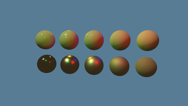
Built from PR #243 (merged as 05ebea3), #245 (a5bfa81), #246 (877ea94) and #247 (db3ef10; read at its last code commit, 6764239), with ticket #199 and its comments, spec #188 and ADRs 0019, 0020 and 0023. Code facts were read at 6764239, and pre-#199 code at fe08baa. Appendix B is quoted from the glTF 2.0 specification's AsciiDoc source at 7cee0fc (Khronos, CC BY 4.0), KHR_lights_punctual from its README, and the other sources as linked. Where the guide does its own arithmetic, it says so. The demos implement shading.wgsl's formulas in f64 and say where they simplify.